 Angle
Angle Cast Plate
 Diamond Plate
 Flat Bar
 Plate
Plate Round Bar
 Square Bar
 Square Tubing
 Round Tubing
 Angle
Angle Channel
 Diamond Plate
 I Beam
 Round Bar
 Sheet
Sheet Square tubing
 Round Tubing
 Rectangular Tubing
 Plate
Plate Rectangular Bar
 Rectangular Tubing
 Round Bar
 Sheet
Sheet Square Bar
 Square Tubing
Engineering drawings are more than just drawings—they’re detailed illustrations that show all the information and specifications required to build a part using a standard format and terminology. An engineering drawing completely defines every detail of the part, including its:
- Dimensions
- Geometry
- Tolerances
- Materials
- Assembly details
Knowing how to read engineering drawings is an essential skill for any fabricator. This post will provide a basic overview of how to read engineering drawings for home machinists, hobbyists, and new fabricators. Understanding the skills needed to interpret these mechanical drawings accurately is crucial to ensuring successful manufacturing outcomes.
Basic Information
When first learning how to read engineering drawings, the amount of information can seem overwhelming. Where do you start?
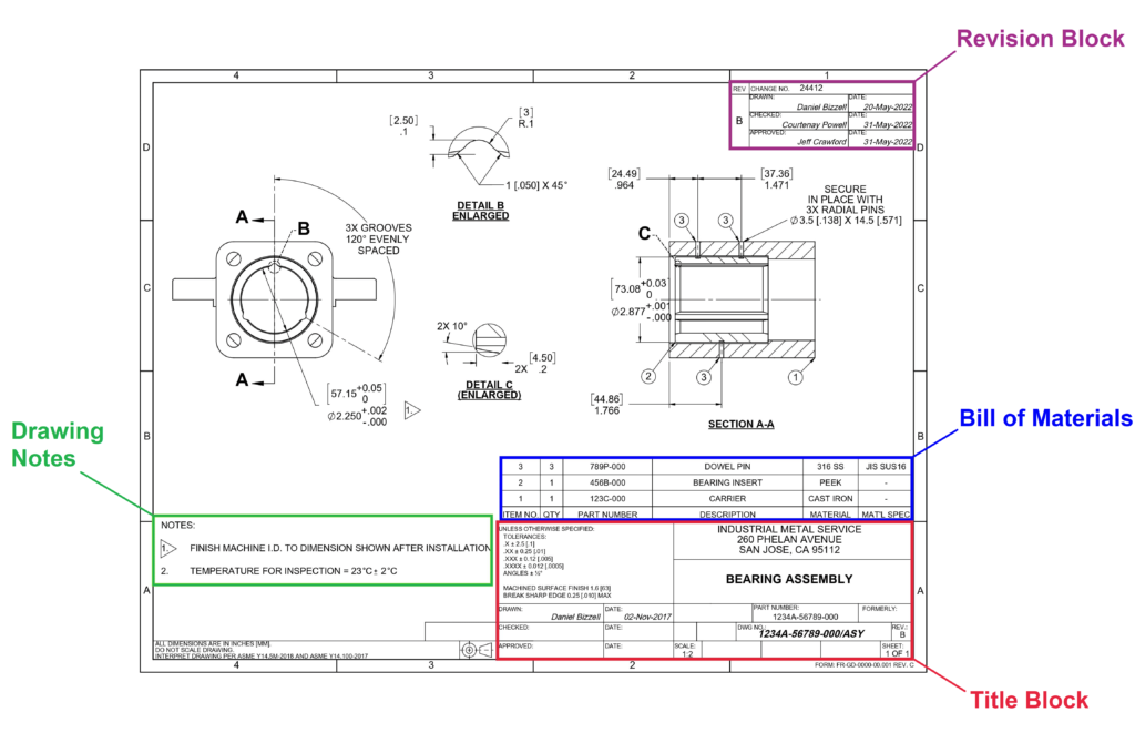
The first things you should look at are the title block, the revision block, the bill of materials, and any notes on the drawing. Understanding the title block information is vital, as it provides context for the entire drawing.
Title Block
The title block is normally at the bottom right corner of the drawing and provides important context and high-level details, such as:
- Part name and number
- General tolerances
- Units (inches, millimeters, etc.)
- Drawing scale
- Revision number
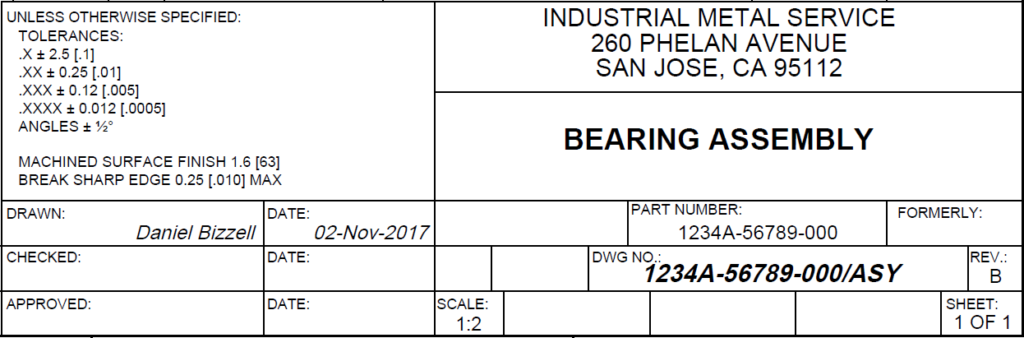
For fabricators learning how to read engineering drawings, the most important details in the title block are the units and general tolerances. Even the most experienced fabricators occasionally plug in the wrong units by mistake, so always double-check whether you’re working in inches, millimeters, or something else. This information may be outside the title block—in this example, the units are defined in the bottom left corner.
General tolerances tell you what tolerances to use for dimensions where no tolerance is specified. For example, in this drawing, a dimension with one decimal place (.X) would have a tolerance of ± 2.5 inches.
When creating mechanical drawings, ensuring that all the items are defined within the specified tolerances is crucial to avoid errors during manufacturing.
Bill of Materials
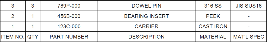
The bill of materials, or BOM, is usually located directly above the title block, in the upper left corner of the drawing, or on the first page of multiple-sheet drawings. It contains a list of all materials, parts, and subassemblies that go into the final part or assembly.
Each material and component listed in the materials block must match the specifications outlined in the technical drawing.
Notes
The next step is to read any notes outside the title block. These contain any information needed to manufacture the part that is not included in the various drawing views and dimensions. Notes are usually located in the lower left corner of the drawing and may include information such as:
- Inspection and testing requirements.
- Surface treatments, platings, or coatings.
- Finishing operations (for example, tempering or heat treating).
- Applicable standards and specifications.
In some cases, these notes might specify third angle projection or first angle projection, which are essential in defining the orientation of views on the drawing.
Drawing Views
Now that we’ve looked at the high-level information of the drawing, we can examine the drawing views. Engineering drawings typically show a front view, side view, and top view of the part.
Other views, such as isometric views, cross sectional views, or enlarged views, may be included if necessary to show all the features of the part.
Often, drawings are divided into zones using a grid of letters and numbers located on the edges of the drawing. Zoning helps to locate specific features on a drawing by referencing their coordinates. For example, Detail B on the drawing above is located in zone D3.
Dimensions
Dimensions are used to define the size, location, orientation, form, or other geometric characteristics of a feature. Sometimes, dimensions will be shown in both U.S. and metric units, in which case the secondary units are in brackets and either above or to the right of the primary units.
Units are not usually shown on the drawing dimensions themselves, so make sure you’re working in the units specified in the title block or elsewhere on the drawing.
Dimensions in parentheses are for reference only and are not controlled in the manufacturing of the part. Mechanical engineers rely on these dimensions to ensure the parts they design and manufacture meet all the specific requirements.
Tolerances
Once manufactured, all parts vary slightly in their actual measurements. Tolerances define the amount of acceptable variation in a specific dimension. When shown, they are next to the nominal dimension. All dimensions must have a tolerance. If one isn’t specified, general tolerances apply.
There are four different types of tolerances:
- Bilateral tolerances show the allowable tolerance in either direction from the nominal dimension (for example, ±.004).
- Unilateral tolerances show the allowable tolerance in only one direction (for example, +.004).
- Limit tolerances show both the maximum and minimum dimensions allowable for a feature.
- Single limit tolerances define one limit dimension (either a maximum or minimum).
How to Read Engineering Drawing Symbols
Tolerances don’t just apply to dimensions—they can also apply to other features like position or flatness. To define these types of tolerances, engineering drawings use a standard system of symbols called Geometric Dimensioning and Tolerancing (GD&T).
There are 14 standard geometric tolerance symbols used in geometric tolerancing as defined by ASME Y14.5:
| Symbol | Name | Description |
 |
Straightness | Controls the straightness of a surface, edge, or axis. It defines the maximum allowable variation of a feature from a perfectly straight line. |
 |
Flatness | Controls the uniformity of a flat surface. It defines a 3D tolerance zone between two parallel planes on either side of the surface. All the points on the surface must be between these two planes. |
 |
Circularity | Controls the shape of a circular feature by defining a 2D tolerance zone between two concentric circles. The circle’s measurements must be within the tolerance zone. |
 |
Cylindricity | Controls a cylindrical feature’s shape by controlling its circularity and axis straightness. |
 |
Profile of a Surface | Defines a 3D tolerance zone around a surface. Points measured on the surface must lie within this tolerance zone. Used for curved or complex surfaces where other tolerances are not easily applicable. |
 |
Profile of a Line | Like surface profile, but defines a 2D tolerance zone around an axis or edge. |
 |
Perpendicularity | Controls the perpendicularity between two surfaces or an axis and a surface. |
 |
Angularity | Controls the orientation of a feature at a specified angle. |
 |
Parallelism | Controls the parallelism of two lines or surface features. |
 |
Position | Controls the exact location and orientation of a feature by defining its maximum allowable deviation from the “true position” based on the model. |
 |
Concentricity | Controls the concentricity of the axis of a circular feature or features about a central datum axis. |
 |
Symmetry | Controls the symmetry of two surfaces about a central datum plane. |
 |
Circular Runout | A 2D measure of a circular profile relative to a datum axis. Similar to circularity, it inspects how well a circular cross-section conforms to a perfect circle. |
 |
Total Runout | Controls the location, orientation, and cylindricity of a cylindrical surface relative to a datum axis. |
These are only the basics of GD&T, but they should be enough to help you understand what you’re making as you learn how to read engineering drawings.
Get Precision-Cut Metal from Your Local Metal Supplier
Whether you’re a machine shop owner, an independent fabricator, or just a hobbyist trying to learn how to read engineering drawings and make your own parts, Industrial Metal Service can help. There’s no need to worry about dimensions and tolerances when you order from us—our metal saws can cut any of our materials to a precise size so you get exactly what you need.
For more than two decades, we’ve built a reputation as a dependable San Francisco Bay Area metal supplier. We also ship aluminum, steel, copper, titanium, and exotic alloys nationwide—cut to size and with no minimum order quantity.
Contact Us